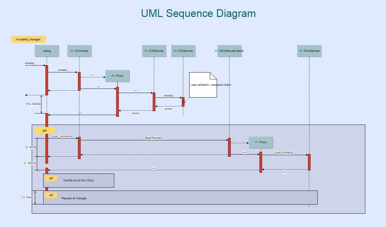

If a caller sends an asynchronous message, it can continue processing and doesn’t have to wait for a response. If a caller sends a synchronous message, it must wait until the message is done, such as invoking a subroutine. Solid arrow heads represent synchronous calls, open arrow heads represent asynchronous messages, and dashed lines represent reply messages. Messages, written with horizontal arrows with the message name written above them, display interaction. Leaving the instance name blank can represent anonymous and unnamed instances. If the lifeline is that of an object, it demonstrates a role. As you read down the lines you will see in detail how certain actions are performed in the provided model, and in what order. After each action is performed, the response or next action is located under the previous one. For example, the actor could request to log in, this would be represented by login (username, password). Messages will often appear at the top or bottom of a system sequence diagram to illustrate the action in detail. When an action line is connected to a lifeline it shows the interaction between the actor or system. Actions are performed with lines that extend between these lifelines. Under each actor or system there are long dotted lines called lifelines, which are attached to them. Reading a sequence diagram begins at the top with the actor(s) or the system(s) (which is located at the top of the page). These models show the logic behind the actors (people who affect the system) and the system in performing the task. In order to construct a system sequence diagram, you need to be familiar with the unified modeling language (UML). The purpose is to illustrate the use case in a visual format. These tasks may include repetitive, simple, or complex tasks. Professionals, in developing a project, often use system sequence diagrams to illustrate how certain tasks are done between users and the system.

All systems are treated as a black box the diagram places emphasis on events that cross the system boundary from actors to systems. Sequence diagrams are sometimes called event diagrams or event scenarios.įor a particular scenario of a use case, the diagrams show the events that external actors generate, their order, and possible inter-system events. Sequence diagrams are typically associated with use case realizations in the 4+1 architectural view model of the system under development. It depicts the processes and objects involved and the sequence of messages exchanged between the processes and objects needed to carry out the functionality.
#UML SEQUENCE DIAGRAM EXAMPLE SOFTWARE#
A sequence diagram or system sequence diagram (SSD) shows process interactions arranged in time sequence in the field of software engineering.


 0 kommentar(er)
